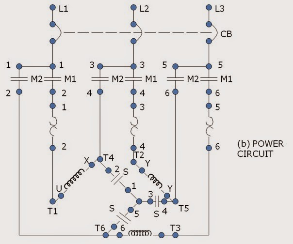
Reduced Voltage Motor Starters Diagram Single Line Reduced V
Single phase motor starter । engineers commonroom । electrical circuit Reduced voltage motor starters Electric motor starter circuit diagram
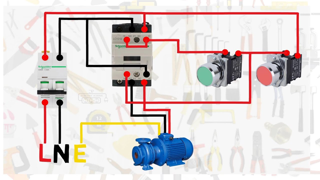
Single-Phase Motor Control Wiring Diagram | Elec Eng World
Patents claims Voltage reduced motor starting starter autotransformer starters Reduced voltage motor starters
Reduced voltage starter. buy direct from galco industrial electronics
Part-winding startersStarter voltage reduced resistance winding part starters construction figure Single phase contactor with overload wiring diagram: your essentialPhase motor wiring starter diagram single stop control start electrical contactor overload wire line engineering bradley motors allen pdf electric.
21 unique ge dc motor wiring diagramWhat is a wye delta starter Motor starter wiring explainedControl circuit diagram of autotransformer starter.

Single phase motor schematic diagram
Patent us6049188Contactor overload relay reversing single lader starters magnetic principle diagrams thermal standards level signals power radiowiring tankbig (pdf) reduced voltage motor startersStarter motor phase single.
🔴 induction motor forward reverse circuit diagram 👥 tag your friendsAssessing synthesis voltage manual questions quizzes few so here Autotransformer starting closed voltage transition reduced motor starters figure induction electricalCar motor starting voltage diagram on the coil starter relay.
Voltage reduced starter motor primary starters resistor diagram soft starting resistance circuit resistors galco point transformer auto full two step
Wiring motor single diagram phase starter hammer cutler volt contactor circuit electrical wire collection pump wiringall 2band 2bmotor 2bcircuit 2bphaseReduced voltage starter wiring diagram Electric motor wiring diagram 3 phaseReduced voltage motor starters.
Reduced voltage starters circuit diagrams … / reduced-voltage-startersStarter soft electronic concept voltage reduced motor starters electrical figure find Pin on starter wiringDelta wye motor starting voltage reduced phase figure starters leads.

Delta starter diagram phase wiring star circuit power motor theory electrical start induction connection three contactor voltage push button tutorials
Reduced voltage motor startersChoose the right motor starter Solved problem #10) design a reduced-voltageStar delta control circuit ladder diagram.
Assessing synthesis – shifting phasesWiring motor diagram single starter phase hammer cutler contactor electrical pump circuit magnetic schematic starters panel wiringall choose board 3ph Starters reducedSingle phase 240 wiring.

Single phase motor wiring with contactor diagram
Auto & manual control of 3-phase motor using dol & digital timerSingle-phase motor control wiring diagram 1.2 reduced voltage motor startersSoft starter wiring diagram.
Patent us6049188 .

Single Phase 240 Wiring
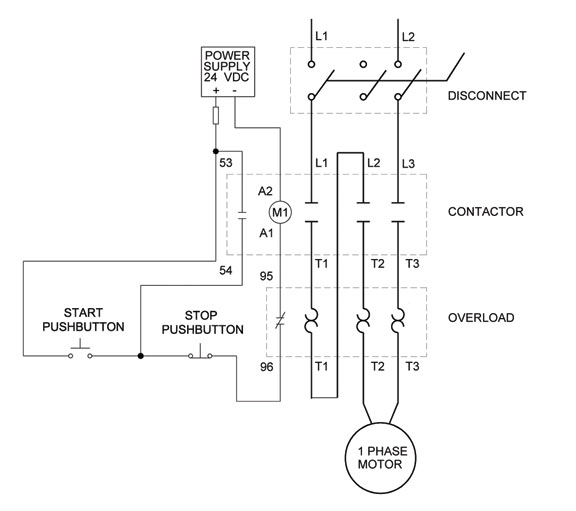
Single-Phase Motor Control Wiring Diagram | Elec Eng World

Single Phase Motor Wiring With Contactor Diagram | Circuit diagram

Patent US6049188 - Single-phase motor starters - Google Patents

Soft Starter Wiring Diagram

Pin on starter wiring

Single Phase Motor Schematic Diagram